
“Get a Ball” Out of Your Woodworking
One of the greatest things about having a woodworking shop is this: When you get an idea for a project (no matter how “goofy” it may seem), you can go into the shop and “have at it”!
And the best part of all is that a woodworking shop is not only a great place to build a project . . it’s a fantastic place for stimulating ideas, as well! Don’t you just love woodworking?
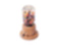
MARK V owner Troy Todd found this situation to be true for him, as well, when he created this unique, whimsical Wooden Gumball Machine.
Here’s how to make one (refer to the assembly drawing for all part references):
Step 1: Cut out the stock. Follow the list of materials at the end of the article. For best results, we suggest you use a hardwood such as cherry or maple. Cut the round discs (A thru E) using your bandsaw or scroll saw and mark the center of each piece clearly.
Step 2: Drill a 1/4-inch hole in the centers of parts A through E. Mark the part letters on pieces B through E. Now, make the simple clamping jig shown in Figure 1 from a 3/4-inch x 8-inch piece of stock and a 1/4-inch-20 x 3-inch pivot bolt.
Next, stack discs B, C and D over the pivot bolt on the jig with disc B on the bottom. Lay the jig flat on the surface of your MARK V Drill Press Table, with the stacked discs clamped in position with 1/4-inch-20 nut and washer so they won’t rotate.
Locate a point 3/4-inch in from the center of your discs and drill a 5/8-inch diameter hole. Set your drill press stop to drill all the way through discs D and C . . . but only half-way through disc B. Drill your 5/8-inch hole.

Step 3: Rout the slide lever slot on disc C by first marking off the 2-3/4-inch arc on the edge of the disc. Tilt your MARK V’s table 90-degrees so its surface is parallel with the machine’s way tubes, then clamp the jig to the table surface as shown in Figure 1 . . . so the point of your drill bit is in exact left-right alignment with the centerline of your pivot bolt.
Mount disc C over the pivot bolt and drill a 1/4-inch diameter by 1-inch deep hole at each end of your drawn arc. Next, use your MARK V’s Router Attachment with a 1/4-inch Bit to rout a 1-inch deep groove, connecting the two 1/4-inch holes you just drilled. Caution: Do this in shallow, 1/8-inch deep passes to ensure the smoothest slot.

Step 4: Cut out the center of disc C with a 2-1/2-inch hole saw or scroll saw. While you’re at it, also cut out the center of the body piece (E) and set piece E aside.
Now, take the center (scrap) stock you just cut out of disc C and clamp it down over the jig pivot bolt. Drill a 1/4-inch diameter x 3/4-inch deep hole at the centerline for the slide lever, next to the 5/8-inch vertical hole as shown in Figure 2.
Step 5. Chamfer the 5/8-inch diameter holes on discs C & D. Use your Drill Press with a 1-inch countersink bit. Also locate and create a countersink “dimple” on piece A to catch the gum ball as it exits the hole in the side of disc B.

6. Drill a 5/8-inch diameter hole for the gum return on disc B. Use your MARK V in Horizontal Boring mode, with the jig clamped to the table surface as shown in Figure 3. Tilt the table 5-degrees so your bit exits through the surface of the disc as it approaches the center.
7. Assemble the machine by first gluing and clamping disc B to disc A with the center pin (F) glued into place. Line up the gum return on disc B with the countersunk gumball catch “dimple” you created in disc A in Step #5 on the previous page.
Next, you’ll need to carefully locate disc C before gluing. First, drop the scrap piece out of the center of disc C over the center pin (F). Next, drop the outer ring of disc C (with the edge groove) into place. Align the 5/8-inch holes in discs B & C and insert the slide lever (G) into the 1/4” hole in the edge of disc C (see Figure 4).
Adjust the outside (C) ring so the lever is at the left-hand end of the slot. Use a pencil to mark the outside of the ring and the glued-up assembly. Now, hold the ring in place with your hand while you check the side-to-side movement of the lever. Remove the slide lever (G) and glue the outer ring into place, being careful not to get any glue on the inside (C) disc.
Once the glue has set up, move the slide lever all the way to the right of he slot. Locate the position of disc D by aligning the 5/8-inch holes. Now, glue disc D into place . . . then attach disc E with glue. Clamp the entire base assembly, and allow the glue to set up for 24 hours.
Helpful Items


Step 8. Turn the base assembly by mounting it to your 3-3/4-inch diameter Lathe Faceplate. Turn the top (E) first, creating a recess that’s the same diameter and approximate depth as the lid of a small mouth canning (Mason) jar. Begin by using a parting tool to establish your dimensions, then a roundnose chisel to complete all the contours. Sand the entire piece while it’s still mounted on the Lathe.
Step 9: Finishing touches. Make the slide lever knob (H) by first drilling a 1/4-inch diameter by 1/2-inch deep hole in one end. Hold the knob with pliers as you drill it. Glue the lever into the knob and allow it to dry. Next, mount the slide lever assembly (pieces G & H) in your Drill Chuck and “turn” the piece using files or sandpaper. Glue the lever assembly into place.
Step 10:. Apply salad bowl finish or paste wax, fill with gumballs and enjoy!
