
Since I'm not sleeping yet anyway I figured maybe I add some more information to this post.
As you recall I was cutting out an opening that is needed so that the drum can run recessed in the bottom. The following photo shows what the cut out looks like. It has to be slightly longer then the drum and be wider then the the drum when it is attached.
[ATTACH]8132[/ATTACH]
If you are still a little lost keep reading it will soon be getting clearer. Now let's address the dust control, assuming we will be making some saw dust with what ever this turns out to be. Well if only we had an opening to which a vacuum could be attached... if only... wait, in the last picture didn't I see a hole??? Let me look more carefully.
[ATTACH]8133[/ATTACH]
Looks like we got lucky and have a place where the sawdust can go with a little help. Now didn't that work out slick???
Now it is time for a test fit. The width must allow both pillow blocks to rest on the plywood, the cut out much fit the length and width of the drum and the drum must be able to go low enough so the pillow blocks are laying flat on the plywood. Things are progressing.
[ATTACH]8134[/ATTACH]
Next the attachment points can be found and holes drilled.
[ATTACH]8135[/ATTACH]
This is followed by inserting some 3/8-16 threaded inserts. I have a t-handled wrench designed to screw them in so it doesn't take long.
[ATTACH]8136[/ATTACH]
The next post should be able to finish progress to date.
Ed
Basic or not so, general interest??
Moderators: HopefulSSer, admin
- Attachments
-
- DSCF7560sc.jpg (53.26 KiB) Viewed 4660 times
-
- DSCF7562sc.jpg (49.34 KiB) Viewed 4650 times
-
- DSCF7563sc.jpg (63.73 KiB) Viewed 4651 times
-
- DSCF7564sc.jpg (38.1 KiB) Viewed 4650 times
-
- DSCF7565sc.jpg (42.88 KiB) Viewed 4650 times
{Knight of the Shopsmith} [Hero's don't wear capes, they wear dog tags]
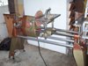
After finishing all the inserts I went ahead and assembled the pillow blocks to the plywood. I had gotten as far as I expect to for the day but I wanted to apply power to see what would happen.
I clamped the plywood down and put the power coupler in place and fired up the shopsmith. So far so good!
[ATTACH]8137[/ATTACH]
As I was taking it down I wanted to shoot some pictures of the bottom so you can see how the drum sets in the plywood. These are the two shots I got but they don't do a very good job of showing what I was hoping to show but maybe they will do a good enough job... (if you are still not clear on this I give it another try).
[ATTACH]8138[/ATTACH]
[ATTACH]8139[/ATTACH]
While I'd like to keep going on this I can not for the next little while. Think of this as your spring break. I will try and do one or two more post on things like operational speed and velcro in the next few days and then when I get back on the project I will let you know with some more posts.
Ed
- Attachments
-
- DSCF7567sc.jpg (75.72 KiB) Viewed 4942 times
-
- DSCF7569sc.jpg (41.28 KiB) Viewed 4945 times
-
- DSCF7568sc.jpg (39.59 KiB) Viewed 4943 times
{Knight of the Shopsmith} [Hero's don't wear capes, they wear dog tags]
Hi,
Chuck got lost on some of the dimension stuff I was doing back a few posts and it likely a few more of you did too but just kind of fluffed over it. I'll try to get back to that soon so stay tuned. I'll add some sketches that should clear it up for you all I hope.
But first I wanted to visit the issue of how fast the drum should be running at least in light of what we now know.
A machine like this that is a commercially offering is a starting point. What we know about the machine is the drum is 2" in dia. I don't know if that is with or with out sandpaper but for now who cares. The motor they mention is a 1725 rpm so from those facts we can do some math.
Math wise we know that the circumference of a circle is pi*d, pi being about 3.1416(plus a lot more digits). You can do this a lot of ways but I hope this is the simplest to follow, so the circumference is about 6.2832", in other words if you put a tape measure around the drum it would read something close to this number. Now let's start spinning the drum, if it was running at 1 rpm it would have a linear distance of 6.2832", if it were 10 rpm then it would be 62.832", 1000 rpm it would be 6283.2" or at 1725 rpm it would be 10,838.52". This would look like (pi*dia of drum*rpm of motor= distance) 3.1416*2*1725 = 10,838.52.
Using this idea we now want to work back to find the rpm to use with a 3.3" dia. drum. If we rearrange the terms it would be (distance/(pi*dia of drum)= rpm of motor) 10838.52/(3.1416*3.3) = 10838.52/10.3673 = 1045 rpms or so.
Now if you had a new powerpro I guess you would just dial in the speed but since none of us do we need to find the letters in that range. The letter would be "D" at 1050 rpm. This is going to be at least a starting spot.
Ed
{Knight of the Shopsmith} [Hero's don't wear capes, they wear dog tags]
As promised this post will go over some of the dimensions that may have confused you in post No.36.
So you don't have to go back this is a quote from that post with additional information:
"These are massive over kill, 200 series with ball bearings but were on the surplus market so it was price over what was really needed. They also have some information sheets which have dimensions such as the distance from the mounting to the center of the shaft. "H" is 1.311", if we add a piece of plywood with a nominal .75" and then set this plywood on the shopsmith main table then the shaft center would be 2.061 or so above the main table. You may remember a posting I did a while back asking what the dimension was on various shopsmith units from the main table to the center of the shaft??? You can check that out at:
http://www.shopsmith.net/forums/showthread.htm?t=5188
All of dimension provided were greater then the 2.061 so that part was looking good. However that was only part of the design."
The drawing has the dimension of the base to center of the bearing shown as the 1.311 dimension. The plywood is now adjusted to .718 (23/32) rather then the nominal .75" I mentioned the first time. So now when the dimensions are combined we can see the center of the shaft is 2.030" above the shopsmith main table. Again all respondents indicated the various models could accommodate this dimension.
[ATTACH]8166[/ATTACH]
"Next I was looking for a piece of PVC pipe for the drum, as a start the 3" PVC measures 3-1/2" in diameter. If we imagined the pipe had a center line it would run 1-3/4" from that line to the outside of the pipe. Now look back at the "H" dimension.... see the problem?? We have only 1.311" of from the center line of the pillow block to the plywood but need at least he 1-3/4". Solution is to cut out the plywood where the pipe needs to go, plus a little. Just to check how close we are getting to the main table all we need do is subtract 1.311 from 1.75 to find .439". In addition we used 3-1/2" but after turning the pipe down we know it is even less now, so all is looking good."
This second image shows the "drum" at 3-1/2" and that without the cut-out in the bottom plywood this could not work. The other option might have been to add spacers below the pillow blocks until the "drum" would clear the plywood. The problem then would be with having enough to much height to be able to sit on the shopsmiths main table...
[ATTACH]8167[/ATTACH]
Hope this clears up and questions on the dimensions.
Ed
- Attachments
-
- dim 1.jpg (26.8 KiB) Viewed 4871 times
-
- dim 2.jpg (28.47 KiB) Viewed 4870 times
{Knight of the Shopsmith} [Hero's don't wear capes, they wear dog tags]
-
JPG

- Platinum Member
- Posts: 34643
- Joined: Wed Dec 10, 2008 7:42 pm
- Location: Lexington, Ky (TAMECAT territory)
Stick around for a wider home brew sand flea!;)
╔═══╗
╟JPG ╢
╚═══╝
Goldie(Bought New SN 377425)/4" jointer/6" beltsander/12" planer/stripsander/bandsaw/powerstation /Scroll saw/Jig saw /Craftsman 10" ras/Craftsman 6" thicknessplaner/ Dayton10"tablesaw(restoredfromneighborstrashpile)/ Mark VII restoration in 'progress'/ 10E[/size](SN E3779) restoration in progress, a 510 on the back burner and a growing pile of items to be eventually returned to useful life. - aka Red Grange
I was hoping to get more of this done but I have been in preparation for a trip to the UP of MI and that has been taking a lot of my time. Two really nice days ahead and I'm hoping for enough time and energy to cut some more wood...
Today I finished the oil change w/filter and tire pressure checks/fills and window washer fill etc and still had a small amount of light left in the day to do a few things on this project.
As you may or may not recall I had left the drum without being attached to the wheels. So today's project was to drill and screw in the screws. I used a tapered drill and set the depth of the countersink to just have the screw head below the rounded surface of the drum. It took a few tries to get it just right along with the depth of the drill. I used some test holes in other material before working on the drum.
The bit looks like this:
[ATTACH]8201[/ATTACH]
The PVC material ended up having to be cleaned out after each drilling operation... only 9 hole but I sure would look for a better way to do this if I had a lot to do.
I wanted to use brass screws and since they are a tapered screw I wanted to use the tapered drill, since the drills have the ability to both control dept of drill and countersink was the reason to go this way. I guess I'd do it again so long as it was so few screws.
This is what it looks like after they are installed:
[ATTACH]8202[/ATTACH]
One of the next operations will be the velcro... I'm thinking since the velco covers the holes and since the idea is the sandpaper spins up to do the sanding this should not be a problem. If one were going to do a thickness sander and were to for go the velcro it still might work, and if not maybe some bond or epoxy could be used. Have to see how it all works out.
Ed
- Attachments
-
- DSCF7592sc.jpg (34.88 KiB) Viewed 4752 times
-
- DSCF7593sc.jpg (15.76 KiB) Viewed 4753 times
{Knight of the Shopsmith} [Hero's don't wear capes, they wear dog tags]
After a great trip to the UP of MI and catching up on a few things around the yard and house I am now back on this project.
One of the things I planned to do was to laminate the top. Using the Baltic birch and a top and bottom layer of solid color "Formica". So this week I went out shopping for some laminate. I found out two thing, one the solid colors are no longer "in" and you have to order them, and two the prices are a lot higher then they use to be.
The top is about 2' by 2' so the best fit I could get would be a 30" x 48" piece as a stock size. It would cost about $40 for a piece that size. Since cost of materials is one of the constrains this put a large dent in my forecasts.
At this point I had purchased the plywood on sale for $19.99 and would need to spend another $39.90 for a total of near $60 just for the top. I then found Rockler had Phenolic faced plywood on sale for $29.99. I ordered a sheet and that will now be the material for the top. I haven't cut the other sheet yet so it will now go in to storage for another project.
This isn't holding me up as I have parts to cut, and some assemble to do before I start on the top. The next decent day I'll get them cut and before long I'll be in to testing...
Ed
{Knight of the Shopsmith} [Hero's don't wear capes, they wear dog tags]
-
johnmccrossen
- Gold Member
- Posts: 173
- Joined: Wed Feb 21, 2007 8:09 pm
- Location: Washington
Ed, I always appreciate your sharing of your projects and ideas. I recently was looking for some plain white laminate to add to some drawer bottoms and was suprised by the cost and unavailability. Thanks for the Rockler tip, I had not noticed that before. I will check them out to see if they have 1/4" laminated ply. John McCrossen
John McCrossen
Everett, Wa.
1954 Mk 5 SN 269454, 1955 Mk 5 SN 316013, 1960 Mk 5 SN 360792, 1962 Mk 5 SN 380102, Magna band saw, (2) jointers, (1) belt sander, (1) air compressor, (1) jig saw, (1) strip sander, (1) 20" scroll saw, DC 3300 dust collector, Sawsmith RAS, Craftsman table saw, 13" DeWalt planer, Triton 3 1/4 HP plunge router & table
Hi,
The other day I got to cutting up some more parts for the project. I didn't take any photo's of the process as I'm guessing most you you would know how to cut some parts out of a hunk of plywood. I also did some short runners out of oak that fit the shopsmith main table miter slots. Again I'm thinking most of you can manage that task. I also cut the continuous hinge to length... maybe I should have shown how I do that? Well to late for this project.
I was slowed down a bit when I looked at how bad looking my blades had gotten... yea time to do a clean up. I like to soak them in baking soda for about 8 hours so I got two started and kept the other two dirty ones for use that day.
The following picture shows the components that are now ready for assembly.
[ATTACH]8592[/ATTACH]
I know that's pretty exciting but I hope you can deal with it.
The good news is that the new top material arrived today from Rockler and I think it is going to work really well for the project, perhaps better then what I originally planned with the laminate and plywood.
Not a lot to look at but in case you have never seen the material:
[ATTACH]8593[/ATTACH]
Since I had some of the parts cut I did the assembly of the two rectangular boxes that mount to the lower assembly. Nothing fancy here, just butt joints with glue and tacked with some nails. They are just sitting in position on the base so I could check the fit and mark for drilling. I'm thinking that will happen tomorrow. Here is what it is starting to look like:
[ATTACH]8594[/ATTACH]
[ATTACH]8595[/ATTACH]
Sorry for the slow progress but to many other things going on to spend full time on this project.
Ed
- Attachments
-
- DSCF8104sc.jpg (82.76 KiB) Viewed 4594 times
-
- DSCF8244sc.jpg (58.04 KiB) Viewed 4592 times
-
- DSCF8249sc.jpg (72.12 KiB) Viewed 4590 times
-
- DSCF8250sc.jpg (72.48 KiB) Viewed 4590 times
{Knight of the Shopsmith} [Hero's don't wear capes, they wear dog tags]