Hi all: I am new to the forum, but have been a Mark V owner since 1984 when I purchased a new 510 system and various accessories. My machine sat unused from 1985 until 2007, I have now started using the equipment almost daily! I love it!
My son recently bought a 1958 500 that has a GE 3/4 hp motor, I found that a all of the wiring was bad and was stupid enough to disconnect all of the wiring before making a schematic. I purchased a new power cord that has three wires, the switch has two terminals in and two out. On the motor there is a round two terminal thing and below there is a square terminal box that has 4 terminals on one side and 1 on the other side. I think (I am not at the machine right now) that there are three wires coming from the motor. Can anyone give me a drawing of which wire goes where before I blow another circuit breaker?
1958 shopsmith wiring
Moderators: HopefulSSer, admin
-
curiousgeorge

- Platinum Member
- Posts: 880
- Joined: Tue Feb 27, 2007 1:00 am
- Location: Fort Worth, Texas
Hello yellowruf, welcome to the forum. I'm sure one of our local gurus will give you more help, but the attached PDF's might help get you started. Hope this helps a little. I got these files from here:
http://www.allinonewood.com/?page=shop/serviceadvisor
It's the Canadian Shopsmith site and loaded with good information.
http://www.allinonewood.com/?page=shop/serviceadvisor
It's the Canadian Shopsmith site and loaded with good information.
- Attachments
-
 replacingthemarkvswitch.pdf
- (201.8 KiB) Downloaded 3156 times
-
- replacingthemarkvpowercord.pdf
- (402.05 KiB) Downloaded 3354 times
-
- replacingthemarkvmotor.pdf
- (504.99 KiB) Downloaded 3138 times
George
Ft. Worth, TX.
Go TCU Froggies
Ft. Worth, TX.
Go TCU Froggies

Watch:
http://www.shopsmithacademy.com/SS_Arch ... Switch.htm and
http://www.shopsmithacademy.com/SS_Arch ... rn_Pt2.htm (last part, where we show how to replace the power cord)
With all good wishes,
http://www.shopsmithacademy.com/SS_Arch ... Switch.htm and
http://www.shopsmithacademy.com/SS_Arch ... rn_Pt2.htm (last part, where we show how to replace the power cord)
With all good wishes,
Nick Engler
http://www.workshopcompanion.com
http://www.workshopcompanion.com
-
dusty

- Platinum Member
- Posts: 21368
- Joined: Wed Nov 22, 2006 6:52 am
- Location: Tucson (Wildcat Country), Arizona
yellowruf,
I have no experience with that age machine but if you give us a better description of the three wires coming from the motor, I think help is available here.
What color are they. What would be really good is if you could give us a photo image.
As for the switch, which is a DPST, it has four wires. Ultimately, the black and white wire from the line cord connects to two of them and two wires from the other side go the motor (I would expect them to be black and white also).
Previous posts to this thread give you good instructions and some images to guide this process.
The green wire from the line cord is a safety ground and should be connected to a screw somewhere on the metal motor housing. I would expect it to also be green.
The motor terminal block (which you indicate has five terminals and three wires) is the tricky part. Pictures would help. Wire color might help. An answer that there are four wires coming from the motor (1 white, two black and one red) would clear up a lot. Let us know.
CAUTION:
When you do get this all wired and turn it on if the motor dosn't work instantly - TURN IT OFF INSTANTLY. Don't let the motor hum. If the motor is allowed to sit and hum there is a good chance that you do serious damage. I got one sitting on my bench right now that I believe that happened to.
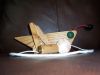
The attached picture IS NOT of the motor you have but a picture of this sort from your motor would help. This is a Shopsmith motor of a later vintage and this motor is reversible. For those reasons it should not be used as a guide to connecting your motor wires.
PS added at 2:00am
Are any of the terminals on the motor labeled. The power cord would connect to something like L1 and L2 or L1 and L4 if they are labeled?
If you have terminals labeled A and B or Tab A and Tab B, those are the run windings and would connect to two of the wires coming out of the motor.
I have no experience with that age machine but if you give us a better description of the three wires coming from the motor, I think help is available here.
What color are they. What would be really good is if you could give us a photo image.
As for the switch, which is a DPST, it has four wires. Ultimately, the black and white wire from the line cord connects to two of them and two wires from the other side go the motor (I would expect them to be black and white also).
Previous posts to this thread give you good instructions and some images to guide this process.
The green wire from the line cord is a safety ground and should be connected to a screw somewhere on the metal motor housing. I would expect it to also be green.
The motor terminal block (which you indicate has five terminals and three wires) is the tricky part. Pictures would help. Wire color might help. An answer that there are four wires coming from the motor (1 white, two black and one red) would clear up a lot. Let us know.
CAUTION:
When you do get this all wired and turn it on if the motor dosn't work instantly - TURN IT OFF INSTANTLY. Don't let the motor hum. If the motor is allowed to sit and hum there is a good chance that you do serious damage. I got one sitting on my bench right now that I believe that happened to.
The attached picture IS NOT of the motor you have but a picture of this sort from your motor would help. This is a Shopsmith motor of a later vintage and this motor is reversible. For those reasons it should not be used as a guide to connecting your motor wires.
PS added at 2:00am
Are any of the terminals on the motor labeled. The power cord would connect to something like L1 and L2 or L1 and L4 if they are labeled?
If you have terminals labeled A and B or Tab A and Tab B, those are the run windings and would connect to two of the wires coming out of the motor.
- Attachments
-
- Power Station Wired Normal.JPG (154.66 KiB) Viewed 21017 times
"Making Sawdust Safely"
Dusty
Sent from my Dell XPS using Firefox.
Dusty
Sent from my Dell XPS using Firefox.
I would suggest to any one replacing a switch, power cord or motor. DO NOT remove the wires, cut them off and leave about two inches of wire on each terminal. That way when you start replacing the wires. You just remove one old wire, connect the new one. Untill you have all of the new ones connected.
SS 500(09/1980), DC3300, jointer, bandsaw, belt sander, Strip Sander, drum sanders,molder, dado, biscuit joiner, universal lathe tool rest, Oneway talon chuck, router bits & chucks and a De Walt 735 planer,a #5,#6, block planes. ALL in a 100 square foot shop.
.
.
Bob
.
.
Bob